Views: 0 Author: Site Editor Publish Time: 2026-06-16 Origin: Site
Quick answer:
A DC submersible pump curve plots flow rate against total head, revealing how a pump performs across its operating range. High-flow pumps suit wide, shallow systems with large volume demands, while high-head submersible pumps are built for deep wells and high-elevation scenarios. Matching the curve to your system curve is the core of correct pump selection.
Choosing the wrong DC submersible pump costs more than money. It costs time, system efficiency, and in some cases, the pump itself. Yet the selection process is routinely simplified to a single question: "How deep is the well?" That single metric misses the bigger picture.
The pump curve—sometimes called a performance curve or H-Q curve—is the real foundation of any professional submersible pump selection guide. Once you know how to read one, the difference between a high-flow pump and a high-head submersible pump becomes immediately clear. More importantly, you'll know exactly which one fits your application.
This guide breaks down how DC submersible pump curves work, what each axis tells you, and how to apply that knowledge to make the right call between high-flow and high-head configurations.
A pump curve is a graphical representation of a pump's hydraulic performance. For a DC submersible pump, it typically plots:
X-axis: Flow rate (Q), measured in liters per minute (L/min), cubic meters per hour (m³/h), or gallons per minute (GPM)
Y-axis: Total dynamic head (H), measured in meters (m) or feet (ft)
The curve itself runs from left to right, starting at maximum head (zero flow, also called shutoff head) and descending toward maximum flow (zero head, also called free delivery). Every point along that curve represents a stable operating condition.
Most performance charts also include secondary curves overlaid on the H-Q graph:
Efficiency curve (η): Shows at which flow rate the pump operates most efficiently. This is the pump's Best Efficiency Point (BEP).
Power curve (P): Indicates motor shaft power consumption at different flow rates.
NPSH curve: Represents the Net Positive Suction Head required to avoid cavitation.
For DC submersible pumps specifically—often solar-powered or battery-driven—the power curve carries extra weight. Unlike AC pumps, DC systems have a fixed energy budget, so operating near the BEP directly affects runtime and battery longevity.
Reading a DC submersible pump curve is straightforward once you understand the relationship between its components.
Your system has its own resistance curve, also called the system curve. This curve describes how much head is required to push water through your pipes at different flow rates. The point where your system curve intersects the pump curve is the operating point—the actual flow and head your pump will deliver in that specific installation.
If the operating point sits far to the left of the BEP, the pump is under-loaded and running inefficiently. If it sits far to the right, the pump is overloaded, which causes excessive power draw and accelerated wear.
Shutoff head tells you the maximum elevation the pump can push water against with zero flow. This is critical for high-head applications like deep wells or elevated storage tanks.
Free delivery tells you the maximum flow the pump can produce when there is no head resistance. This matters most in high-flow, low-head scenarios like surface irrigation or drainage.
Always confirm your operating point falls within 80–110% of the BEP flow range. Operating outside this window—even if the pump technically delivers the required flow and head—significantly reduces efficiency and service life.

A high-flow DC submersible pump produces a large volume of water per unit of time, but typically at a relatively low total head. On the pump curve, these models display a shallow, wide H-Q curve—meaning head drops gradually as flow increases, and the pump remains productive across a broad flow range.
Typical high-flow pump curve characteristics:
Shutoff head: Low to moderate (often under 30–50 m)
Maximum flow rate: High (often exceeding 10 m³/h for mid-size units)
Curve shape: Gradual slope, flat profile
Best suited for:
Surface irrigation systems covering large areas
Flood control and drainage applications
Water transfer between reservoirs at similar elevations
Fish farming and aquaculture recirculation systems
Shallow boreholes with high yield
The selection logic here is straightforward: when your system demands volume over pressure, a high-flow pump's curve will align closely with a shallow, high-flow system curve, placing the operating point near the BEP.
A high head submersible pump is engineered to push water over significant vertical distances or through high-resistance piping systems. On the pump curve, these units display a steep, tall H-Q curve—the head remains high even as flow rate decreases, and the shutoff head can reach well over 100 meters in multi-stage designs.
Typical high-head pump curve characteristics:
Shutoff head: High (commonly 80–300+ m for multi-stage units)
Maximum flow rate: Moderate to low
Curve shape: Steep drop as flow increases
Best suited for:
Deep borehole and well pumping applications
Elevated storage tank supply (rooftop tanks, hilltop reservoirs)
High-rise building water supply systems
Mountain terrain or long-distance pipeline systems
Pressurized drip irrigation on sloped terrain
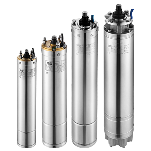
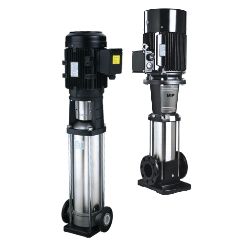
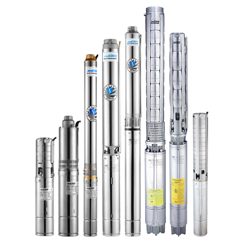
MASTRA's multi-stage submersible pump series—such as the R95 and SP series—are designed for exactly these conditions, stacking multiple impeller stages to build the head required for deep-well and high-elevation applications. When your system curve is steep and your static lift is large, the high-head pump's curve will intersect it at an efficient operating point. A high-flow pump in the same application would simply stall—unable to deliver water past a certain elevation.
The most reliable selection method is to plot both curves together.
Parameter |
High-Flow Pump |
High-Head Pump |
|---|---|---|
Primary advantage |
Large volume output |
High elevation capability |
Pump curve shape |
Flat, wide |
Steep, tall |
Best application |
Shallow, high-demand systems |
Deep wells, elevated supply |
Typical shutoff head |
< 50 m |
80–300+ m |
Efficiency concern |
Over-pressurizing shallow lines |
Under-sizing flow for demand |
DC system impact |
Higher current draw at peak flow |
Higher voltage demand for multi-stage |
A practical rule of thumb: choose a high-flow pump when total dynamic head is below 30 m and volume is the priority; choose a high-head submersible pump when static lift exceeds 50 m or system pressure requirements are significant.
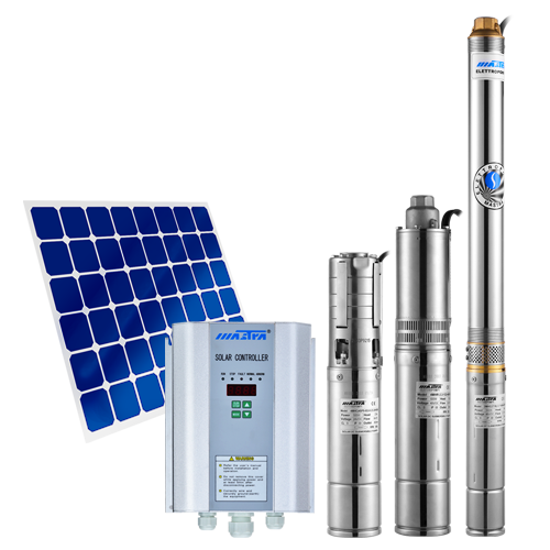
For DC solar pump systems in particular, this decision also affects panel sizing. High-head multi-stage pumps typically require higher operating voltage, which changes the number and configuration of solar panels in an off-grid system.
Reading a DC submersible pump curve isn't a skill reserved for hydraulic engineers. Any procurement professional or field technician who spends time with a few performance charts will quickly develop an intuitive grasp of how pump type, system demand, and operating point interact.
The core principle is consistent: let the system curve lead the selection. Calculate your total dynamic head—static lift plus friction losses—then find the pump whose H-Q curve intersects your system curve at or near the BEP. From there, high-flow or high-head becomes a logical conclusion, not a guess.
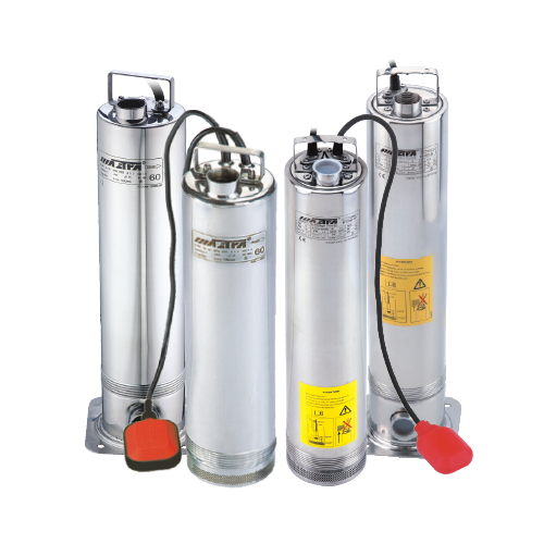
MASTRA (mastrapump.com) offers a comprehensive DC submersible pump range covering both high-flow and high-head configurations, including multi-stage borehole pumps, solar-compatible DC models, and full stainless steel series for demanding water quality conditions. Use the MASTRA Pump Selection tool at mastrapump.com to match your system parameters to the right pump curve—or contact the MASTRA technical team directly for application-specific guidance.
Shutoff head is the maximum head a pump can generate at zero flow. It represents the upper elevation limit the pump can push water to if no flow is required. For deep-well applications, the shutoff head must exceed the total static lift of the installation.
The BEP is located at the peak of the efficiency curve (η curve), which is typically overlaid on the H-Q diagram. The flow rate corresponding to this peak is the ideal operating flow. Design your system so the actual operating point falls within ±10% of this value for optimal performance and longevity.
A high-flow pump can physically operate in a deep well, but its low shutoff head may prevent it from lifting water to the surface if the static water level is deep. The pump will stall before delivering usable flow. A high-head submersible pump is the correct choice for deep borehole applications.
The most common causes are incorrect pipe sizing (increasing friction losses beyond the design point), drop in water table (increasing static head), voltage fluctuations in DC solar systems, or partial pipe blockage. Each of these shifts the actual operating point away from the BEP, reducing efficiency and increasing wear.
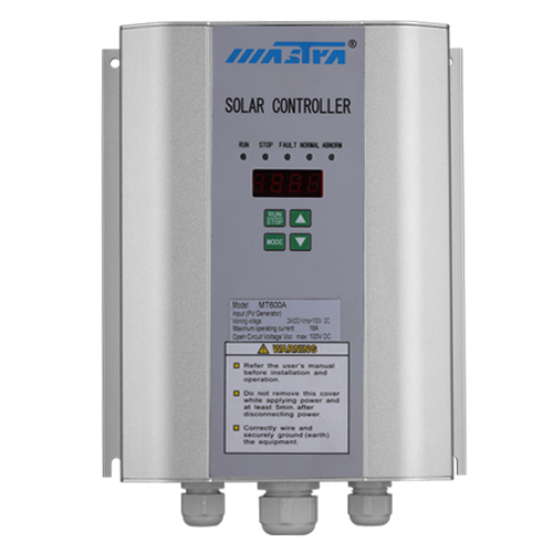
DC submersible pumps powered by solar panels experience variable voltage throughout the day as irradiance changes. At reduced voltage, the motor produces less power, effectively shifting the pump curve downward—reducing both flow and head. Selecting a pump and controller pair with MPPT (Maximum Power Point Tracking) technology minimizes this performance loss.
Yes. Multi-stage submersible pumps stack multiple impeller stages in series, with each stage adding head. This design is specifically used to achieve high shutoff head values unsuitable for single-stage pumps. MASTRA's SP and R95 multi-stage series exemplify this configuration for deep-well and high-pressure applications.